Developing a diagnostic game plan
We’ve all heard the saying “knowledge is power,” but knowledge can be quite profitable, too. A rock-solid technician is one that has honed their craft as being a problem-solver. We often think of that person as one who can “fix” anything. Although that may be true, there is certainly more to it than being good with your hands. Having an understanding of the systems and the components that they are comprised of, along with the goal of that system, is what it takes to be successful in today’s world of automotive service, repair, and especially diagnosis. Learning to leverage service information in your diagnostic approach can yield efficiency and success.
While it may seem counter-intuitive to step back and tread slowly (especially from a “flat-rate” perspective), separating oneself from the vehicle, creating a game-plan, and seeing it through will keep you focused on the “facts.” This, in turn, will create efficiency without missing any steps. When I approach a vehicle, I never do so without having a game plan. For me, this means gathering pertinent data about the components that make up the system. I look to address:
- How are the components configured to carry out a goal?
- What is that goal?
- How do we know whether the goal was achieved/how is the system monitored?
- What are some parameter IDs (PIDs) that can give me easy-to-grab insight into the system’s functionality?
These items can yield plenty of preliminary information about any problem, on any system, in any vehicle. Think for a moment how powerful of a statement that is. Regardless of what is in your bay, it’s this information that will allow you to efficiently solve the riddle. Think of the game plan as nothing more than a series of questions. I invest my time away from the vehicle developing the questions I wish to ask the vehicle. The tools I use and the tests I perform will carry out the questioning process. The results of those tests are the answers I need to make the necessary diagnostic-decisions.
Calling the huddle
I spend my initial diagnostic time understanding the preliminary information. This key information can be found in the service information. Many of us rely on aftermarket sources like AllData, Mitchell 1, Identifix, MotoLogic, etc. Some of us purchase access to OE service information. When it comes to answering the age-old question, “Which source of information is the best?”, the answer is simply all information is the best.
Troubleshooting flow charts – Are they of value?
I recall at one point in my career being let down by troubleshooting flow charts. I was confident that any issue could be solved so long as the flow charts were followed. To my dismay, many times I was left with the only option to substitute a known-good component (like a powertrain control module [PCM] … I’m sure we’ve all been down those winding roads a few times).
I recall being discouraged by the fact that not only was the vehicle’s ailment still present, but I had invested a lot of time and money and was no further along than I was hours ago. How could this have happened? What was the missing element that prevented me from being successful? After all, the flowcharts were written to help me fix the vehicle by the same people that designed the vehicle, right?
WRONG! The flowcharts are there to help the average factory-trained technician repair a vehicle (that’s under warranty), in the most financially efficient way, the majority of the time. The flowcharts are written concerning the most-likely failures the system(s) might encounter. They are not written concerning our wallets. This is why we may spend so much time with disassembly/reassembly rather than a pursuit with logic. Of course, we realize that the engineers who design the flowcharts aren’t necessarily the same engineers who design the systems. There tends to be a disconnect between the two.
Over the years I’ve learned that there is key information within those flowcharts that I use every day to streamline my diagnostic approach. Reading the steps and following them blindly is never recommended. Understanding what each of the steps is asking for will give you a good idea of what the electronic control unit (ECU) is looking for and anticipating, as well as a logical approach. One example is resistance specifications – keeping in mind that voltage drop, resistance, and current flow all relate to one another. Knowing what the resistance specification is calling for will allow us to anticipate how much current flow the circuit being monitored should draw. This is how circuits are being evaluated for performance and the reason why related diagnostic trouble codes (DTCs) are set when components’ ohmic values fall too far outside of specification. I’d much rather monitor a circuit’s current flow dynamically than to open the circuit and measure for resistance statically. A comparator circuit is used to carry out this task for the ECU’s self-diagnostic strategy (Fig. 1). It serves as a DVOM within the ECU to measure voltage in the circuit under various states of operation. In the example drawn here, a few things can be seen:
- The circuit is of a pull-down design (ECU provides the ground-path to energize the circuit) .
- The circuit is open, and no current should be flowing .
- The DVOM should be measuring/indicating source-voltage (12V) in the circuit’s current state of operation .
(This is what is typically occurring when an ECU sets a DTC about “circuit-low” faults)
The basic building blocks of diagnostics
By viewing not only the wiring diagram but also the theory and operation of the circuit provides for a solid understanding of the circuit functionality and anticipation of what the ECU expects to see on that circuit during its current state of operation (energized or de-energized circuit). The DVOM represents not only where the ECU is monitoring the circuit, but also where we would place our DVOM to monitor the circuit ourselves. In the example in Fig. 1, it should be obvious that the intended state of the circuit would have us anticipate source-voltage at that point under the circuit’s current state of operation. A lot can be derived from just these few pieces of data.
Remember: Having fundamental knowledge of the individual components’ functionality (at the most basic level) can be applied to any vehicle or system out there. Nearly 85 percent of what occurs in any automotive circuit can apply to any vehicle or system. This is due to the physics involved. The remaining 15 percent is how each manufacturer chose to make that circuit function. Combining basic fundamental concepts (from years of practice) along with the tools and testing techniques you’ve learned to employ can help yield a diagnosis efficiently.
A “shift” in strategy
To demonstrate this process, I will use an example: A 2008 Dodge Grand Caravan experiencing a stored DTC P0760 “overdrive-solenoid circuit fault,” along with a transmission functioning in a defaulted-state (no upshift from second gear). The point isn’t necessarily that the vehicle was fixed, but more so how the circuit is being monitored and what techniques I recruited from my experience and fundamental knowledge to prove the fault and repair the vehicle.
I built my game plan away from the vehicle by referencing the service information for DTC P0760. The description and operation of the system and the wiring diagram proved to be all I needed in my arsenal to approach the vehicle and ask of it the questions I would like answered.
- Why won’t this vehicle upshift?
- Why is the DTC set?
- Is the solenoid functional?
- Does the solenoid have everything it needs to function?
The ECU was anticipating seeing an inductive kick. To have a healthy functioning solenoid, the resulting inductive kick from its magnetic field collapsing should be present. Said another way: “If a weak inductive kick is present, the solenoid cannot do its job properly.”
The service information and wiring diagram together tell us where to test, how the circuit functions, what we should anticipate seeing during a test, and what the ECU is looking for to either verify or condemn the circuit for functionality. (Fig. 2) By placing a lab scope at the point indicated on the wiring diagram and referencing it to ground, we could then compare the signature to that derived from testing one of the known-good solenoids, controlled by the PCM.
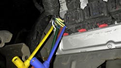
The PCM was located within the left-front fender well of the vehicle (Fig. 3). The appropriate connector and circuits were identified and then probed to be monitored while using the scan tool to carry out a bidirectional control of the individual solenoids. The test results proved that the suspect solenoid circuit did not produce a healthy inductive kick like that of a healthy solenoid circuit (Fig. 4 and 5). It also displayed that the ground side of the circuit was compromised and the PCM was likely at fault. This conclusion was made because the ground path still had significant voltage available on it when energized. That, coupled with the fact that we tested directly at the PCM terminal, concluded that wiring was not an issue. If the PCM’s ground was compromised, the other solenoids’ circuits would’ve suffered as well.
The only logical explanation was a poorly functioning solenoid driver within the PCM itself. To further prove the fault, I continued to monitor the suspect circuit. This time, I supplied an external ground which allowed me to bypass the PCM. This enabled the solenoid to function properly and resulted in a voltage signature that pulled very close to the ground and an inductive kick, similar to the known-good solenoid when the circuit was de-energized. I followed the above test with a measure for current flow from each of the solenoids using the lab scope and a low-amp probe. Seeing that they all drew about the same amperage reassured me that the failed PCM driver had nothing to do with a shorted solenoid-winding.
Being an efficient and accurate diagnostician isn’t about having the fastest hands in the shop. It’s more about using logic. Having fundamental knowledge, built from mastering the basics, and learning to utilize the tools you have comes from practicing on known-good vehicles and investing your free time to better yourself. Take time away from the vehicle to develop a diagnostic game plan derived from the goodies provided by service information. A combination of the wiring diagram and description/operation will yield you the arsenal you need to combat the vehicle and win the battle. It all starts with a little discipline and patience, but it ends with the rewarding feeling of a job well-done.
Brandon Steckler is Technical Editor of Motor Age. He is a working technician at Lykon Automotive in Bristol, Pennsylvania. He has worked in the field for over 18 years and holds multiple ASE certifications.